Hey,
I've been trying to run V-USB on the attiny2313-20PU for the past 72 hours straight. Aside from being unsuccessful, after plugging the circuit in and getting a "device not recognized" error, the tinys are no longer able to be reprogrammed. I'm not sure how I could be burning them out, since I have the 3.6v zener diodes protecting the data lines and the tiny can run up to 5v which is the power supply for USB standard. I thought maybe the fuses could be preventing it from being reprogrammed, but after successfully programming and not plugging it in, I can reprogram it as much as I'd like. After I plug my circuit in however, avrdude says the device doesn't respond (rc=-1) and it throws an error. I'm using a parallel port programmer I made myself, with the correct avrdude argument set to "dapa" I initially thought V-USB wasn't working because of a timing problem, but there must be a bigger problem here since all my chips are frying. Any thoughts? I would really appreciate any help.
Thanks
EDIT: I'm using the circuit from here: http://dangerousprototypes.com/2010/12/22/v-usb-virtual-usb-port-for-avr-microcontrollers/ but with zener diodes from D- to ground and D+ to ground, and 22p caps along the crystal instead of 27p
Burning out attiny's
-
Micha
Re: Burning out attiny's
Where did you connect the zeners? There are none in the schematic you linked here.
-
whistlinwilly
- Posts: 2
- Joined: Mon Aug 01, 2011 8:00 pm
Re: Burning out attiny's
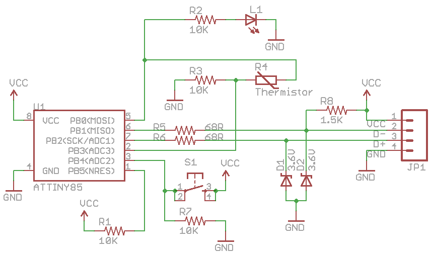
They are connected from D- to ground and D+ to ground like in this schematic here: http://www.insidegadgets.com/wp-content ... ematic.png
This should provide level conversion in place of the two diodes in series in the schematic from my first post correct? (Also, I'm assuming the circuitry connected to pins 5 and 2 are for ADC from some temperature sensor, but are R1 and R7 on pins 1 and 3 necessary? What do they do?)
I'm down to one atmega328p. I've read that its possible to get V-USB working on this, but I'm afraid to plug it into my circuit for fear that it will burn out like my other attiny2313s. Any idea why this is happening? Any way to ensure it doesn't happen?
I think my problem is with the circuitry. How can I troubleshoot this with only a multimeter? My USB cable is somewhat hacked together. Could this be the problem?
-
Micha
Re: Burning out attiny's
That would be ok. Please post a complete schematic corresponding to your circuit.whistlinwilly wrote:They are connected from D- to ground and D+ to ground like in this schematic here: http://www.insidegadgets.com/wp-content ... ematic.png
More or less. See above: post your schematic.whistlinwilly wrote:This should provide level conversion in place of the two diodes in series in the schematic from my first post correct?
R1 is for pulling the reset high -> depends on fuse settings. R7 is for connecting a switch in a complicated way.whistlinwilly wrote:(Also, I'm assuming the circuitry connected to pins 5 and 2 are for ADC from some temperature sensor, but are R1 and R7 on pins 1 and 3 necessary? What do they do?)
See above: post complete schematic. Check your cable twice. Measure the voltage between GND and Vcc. Connect the circuit to a power supply which allows you to limit the current to, let's say, 10 or 20 mA or measure the current consumption with your multimeter.whistlinwilly wrote:I'm down to one atmega328p. I've read that its possible to get V-USB working on this, but I'm afraid to plug it into my circuit for fear that it will burn out like my other attiny2313s. Any idea why this is happening? Any way to ensure it doesn't happen?
I think my problem is with the circuitry. How can I troubleshoot this with only a multimeter? My USB cable is somewhat hacked together. Could this be the problem?
Re: Burning out attiny's
Are you sure they got killed?
I never was able to kill a attiny85.
I went very rough with them! (Reverse power supply and 8V instead of 5.5V).
I more would guess that you might have set the fuses wrong.
I.E. if you want use the internal RC as clock but occidentally set it to external clock.
In that cace you would have to supply it with an external clock, so you can program it again.
I had to do this once. You can easily do it if you have another working CPU or another clock generator like in an oscilloscope.