device descriptor read/64, error -62
Posted: Thu Feb 21, 2008 1:18 am
I'm building the simplest AVR-USB circuit I can, using the atmega324p and based off of the powerSwitch demo, running completely on external 5v power. When I connect it to linux, I get
Feb 20 17:25:02 foo kernel: [66496.580000] usb 1-5: new low speed USB device using ohci_hcd and address 29
Feb 20 17:25:02 foo kernel: [66496.760000] usb 1-5: device descriptor read/64, error -62
Feb 20 17:25:02 foo kernel: [66497.044000] usb 1-5: device descriptor read/64, error -62
Feb 20 17:25:02 foo kernel: [66497.324000] usb 1-5: new low speed USB device using ohci_hcd and address 30
Feb 20 17:25:03 foo kernel: [66497.504000] usb 1-5: device descriptor read/64, error -62
Feb 20 17:25:03 foo kernel: [66497.788000] usb 1-5: device descriptor read/64, error -62
Feb 20 17:25:03 foo kernel: [66498.068000] usb 1-5: new low speed USB device using ohci_hcd and address 31
Feb 20 17:25:04 foo kernel: [66498.476000] usb 1-5: device not accepting address 31, error -62
Feb 20 17:25:04 foo kernel: [66498.652000] usb 1-5: new low speed USB device using ohci_hcd and address 32
Feb 20 17:25:04 foo kernel: [66499.060000] usb 1-5: device not accepting address 32, error -62
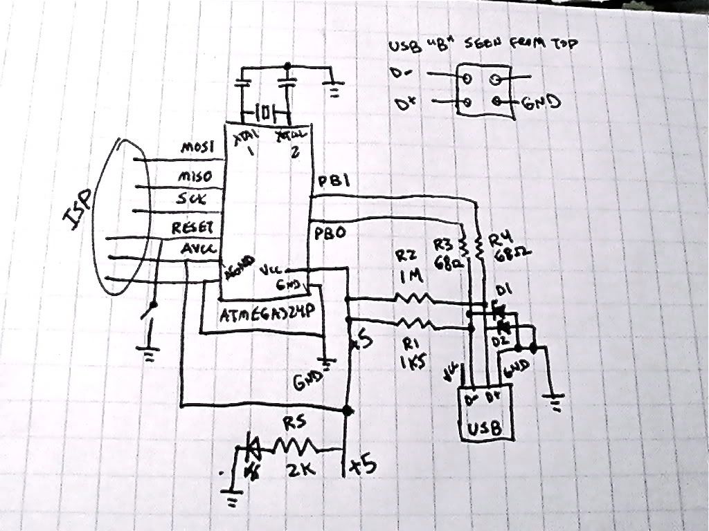
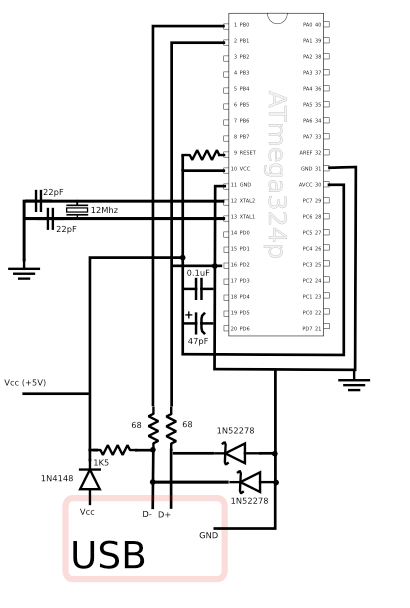
My schematic is here: http://i248.photobucket.com/albums/gg19 ... 0109_2.jpg - the actual circuit has a connection from the D+ line to PD2/INT0, I just forgot to draw it here. Also in this schematic is what I believe is the USB "B" type socket pinout. The diodes are 1N5226B 3v6 zeners, the caps 22p ceramic, and the crystal is a 12Mhz (FOX120-20)
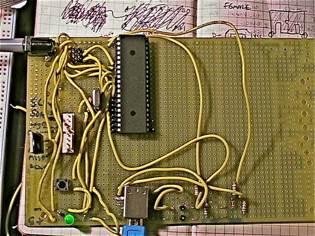
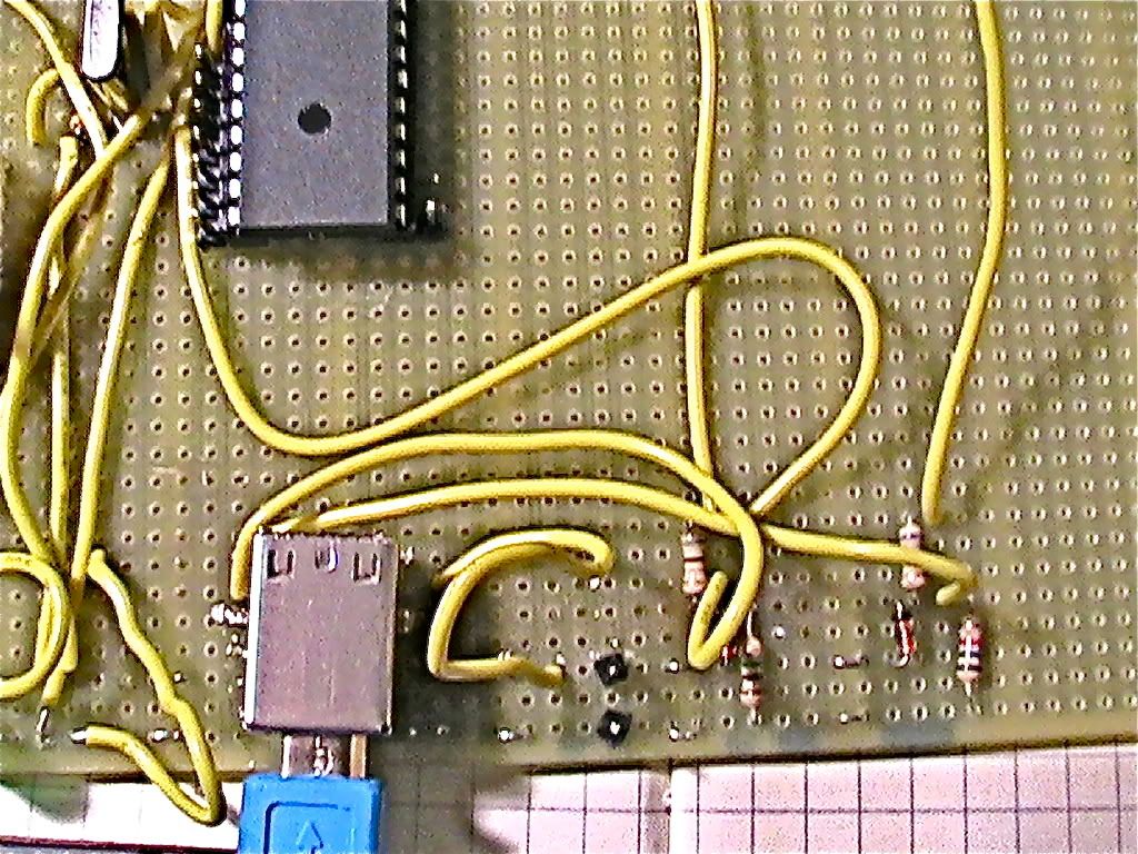
Here are two pictures of the circuit: an overview and a detail of the USB section. http://i248.photobucket.com/albums/gg19 ... G_0107.jpg and http://i248.photobucket.com/albums/gg19 ... G_0108.jpg
The software is the stock powerswitch software, with USB_CFG_IOPORTNAME B, USB_CFG_DMINUS_BIT 0, and USB_CFG_DPLUS_BIT 1, makefile has DEVICE set to atmega324p, uploaded via AVRDUDE. The 12 Mhz crystal has been fused and confirmed to be working through LED timing tests.
I think I did everything right - did I miss something?
Feb 20 17:25:02 foo kernel: [66496.580000] usb 1-5: new low speed USB device using ohci_hcd and address 29
Feb 20 17:25:02 foo kernel: [66496.760000] usb 1-5: device descriptor read/64, error -62
Feb 20 17:25:02 foo kernel: [66497.044000] usb 1-5: device descriptor read/64, error -62
Feb 20 17:25:02 foo kernel: [66497.324000] usb 1-5: new low speed USB device using ohci_hcd and address 30
Feb 20 17:25:03 foo kernel: [66497.504000] usb 1-5: device descriptor read/64, error -62
Feb 20 17:25:03 foo kernel: [66497.788000] usb 1-5: device descriptor read/64, error -62
Feb 20 17:25:03 foo kernel: [66498.068000] usb 1-5: new low speed USB device using ohci_hcd and address 31
Feb 20 17:25:04 foo kernel: [66498.476000] usb 1-5: device not accepting address 31, error -62
Feb 20 17:25:04 foo kernel: [66498.652000] usb 1-5: new low speed USB device using ohci_hcd and address 32
Feb 20 17:25:04 foo kernel: [66499.060000] usb 1-5: device not accepting address 32, error -62
My schematic is here: http://i248.photobucket.com/albums/gg19 ... 0109_2.jpg - the actual circuit has a connection from the D+ line to PD2/INT0, I just forgot to draw it here. Also in this schematic is what I believe is the USB "B" type socket pinout. The diodes are 1N5226B 3v6 zeners, the caps 22p ceramic, and the crystal is a 12Mhz (FOX120-20)
Here are two pictures of the circuit: an overview and a detail of the USB section. http://i248.photobucket.com/albums/gg19 ... G_0107.jpg and http://i248.photobucket.com/albums/gg19 ... G_0108.jpg
The software is the stock powerswitch software, with USB_CFG_IOPORTNAME B, USB_CFG_DMINUS_BIT 0, and USB_CFG_DPLUS_BIT 1, makefile has DEVICE set to atmega324p, uploaded via AVRDUDE. The 12 Mhz crystal has been fused and confirmed to be working through LED timing tests.
I think I did everything right - did I miss something?