Burning out attiny's
Posted: Mon Aug 01, 2011 10:56 pm
Hey,
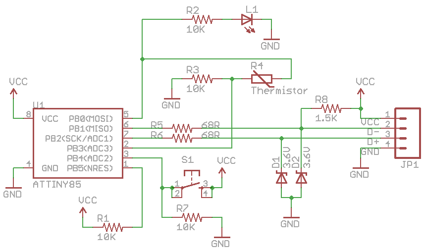
I've been trying to run V-USB on the attiny2313-20PU for the past 72 hours straight. Aside from being unsuccessful, after plugging the circuit in and getting a "device not recognized" error, the tinys are no longer able to be reprogrammed. I'm not sure how I could be burning them out, since I have the 3.6v zener diodes protecting the data lines and the tiny can run up to 5v which is the power supply for USB standard. I thought maybe the fuses could be preventing it from being reprogrammed, but after successfully programming and not plugging it in, I can reprogram it as much as I'd like. After I plug my circuit in however, avrdude says the device doesn't respond (rc=-1) and it throws an error. I'm using a parallel port programmer I made myself, with the correct avrdude argument set to "dapa" I initially thought V-USB wasn't working because of a timing problem, but there must be a bigger problem here since all my chips are frying. Any thoughts? I would really appreciate any help.
Thanks
EDIT: I'm using the circuit from here: http://dangerousprototypes.com/2010/12/22/v-usb-virtual-usb-port-for-avr-microcontrollers/ but with zener diodes from D- to ground and D+ to ground, and 22p caps along the crystal instead of 27p