
Hello,
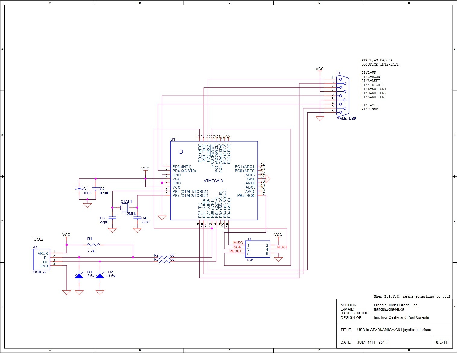
I've got a board already in production that has INT0 connected to D- instead of D+. See: http://www.retronicdesign.com/wp-content/uploads/2012/07/UsbJoyAdapter.jpg
Is it possible to modify the behavior of V-USB to accept this?
I already tried couple of things but it does not work. I doubt there is something to modify in the USBDRVASM.
Anybody experimented that before?
Thanks!
Nitz
INT0 on D- instead of D+

Re: INT0 on D- instead of D+
You define your D pins in the usbconfig.h file (Hardware Config). You can set them up on any pins that are int pins.
Re: INT0 on D- instead of D+
Yup, already done. But it does not work because INT0 is on D- instead of D+.
The important thing mentionned in the code is: "You may
wire the lines to any other port, as long as D+ is also wired to INT0."
Not my case...
The important thing mentionned in the code is: "You may
wire the lines to any other port, as long as D+ is also wired to INT0."
Not my case...
Code: Select all
General Description:
This file is an example configuration (with inline documentation) for the USB
driver. It configures AVR-USB for an ATMega8 with USB D+ connected to Port D
bit 2 (which is also hardware interrupt 0) and USB D- to Port D bit 0. You may
wire the lines to any other port, as long as D+ is also wired to INT0.
To create your own usbconfig.h file, copy this file to the directory
containing "usbdrv" (that is your project firmware source directory) and
rename it to "usbconfig.h". Then edit it accordingly.
*/

/* ---------------------------- Hardware Config ---------------------------- */

#define USB_CFG_IOPORTNAME      B
/* This is the port where the USB bus is connected. When you configure it to
 * "B", the registers PORTB, PINB and DDRB will be used.
 */
#define USB_CFG_DMINUS_BIT      0
/* This is the bit number in USB_CFG_IOPORT where the USB D- line is connected.
 * This may be any bit in the port.
 */
#define USB_CFG_DPLUS_BIT       1
/* This is the bit number in USB_CFG_IOPORT where the USB D+ line is connected.
 * This may be any bit in the port. Please note that D+ must also be connected
 * to interrupt pin INT0!
*/Re: INT0 on D- instead of D+
Ah right you are, I forgot about that caveat. I can't offer much more help on that. Wait around and see if another can.
Re: INT0 on D- instead of D+
Hum... looks like it's not as easy as just changing interrupt polarity...
Help anyone?
Help anyone?
Code: Select all
/* ----------------------- Optional MCU Description ------------------------ */

/* The following configurations have working defaults in usbdrv.h. You
 * usually don't need to set them explicitly. Only if you want to run
 * the driver on a device which is not yet supported or with a compiler
 * which is not fully supported (such as IAR C) or if you use a differnt
 * interrupt than INT0, you may have to define some of these.
 */
 #define USB_INTR_CFG            MCUCR
 //#define USB_INTR_CFG_SET        ((1 << ISC00) | (1 << ISC01))
 #define USB_INTR_CFG_SET        (1 << ISC01)
 #define USB_INTR_CFG_CLR        0
 #define USB_INTR_ENABLE         GIMSK
 #define USB_INTR_ENABLE_BIT     INT0
 #define USB_INTR_PENDING        GIFR
 #define USB_INTR_PENDING_BIT    INTF0
#define USB_INTR_VECTOR SIG_INTERRUPT0 Re: INT0 on D- instead of D+
Sorry - misunderstood.
Re: INT0 on D- instead of D+
Hello,
Actually, it works. This issue was with initial port configuration of the device. Just by changing the pins name and number and the interrupt polarity it's good.
Thanks!
Actually, it works. This issue was with initial port configuration of the device. Just by changing the pins name and number and the interrupt polarity it's good.
Thanks!
Re: INT0 on D- instead of D+
Glad to hear you got it working. Perhaps this topic might be of use to someone else in the future too. Great!
Re: INT0 on D- instead of D+
Glad if this can help!
Now I have some issue with HIDBootFlash that cannot reprogram the boot flash itself. I will post on another topic.
Thanks!
Now I have some issue with HIDBootFlash that cannot reprogram the boot flash itself. I will post on another topic.
Thanks!
-
moefoe
Re: INT0 on D- instead of D+
Could you detail what changes you made to get your code to work on PB0 and PB1?
Thanks.
Thanks.

Re: INT0 on D- instead of D+
What problems are you having with using PB0 and PB1? If you don't also wire one to an interrupt pin, you'll need to be on a device that supports PCINT (pin change interrupt) that you can configure for one of those two pins.